Sawyer travel
Category: Computer Vision, Python
Overview
The goal of this project is to control the Sawyer robot to solve the labyrinth. With the help of computer vision, the start point and the end point can be randomly assigned by color stickers. The joint control is a mixture of velocity control and displacement control. I am responsible for the computer vision part which is to recognize the labyrinth and the end point and to keep tracking the ball and feedbacking to route planning node.
The project is written in Python and with the help of OpenCV. You can find the demonstration video clip below.
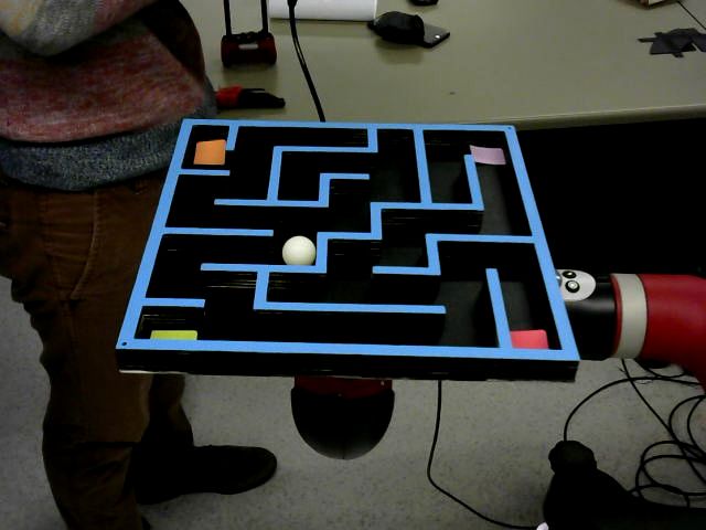
labyrinth information generation
The embedded camera of the the sawyer is with wide viewing angle so it is not suitable for our project considering the angular resolution. So, instead, we mounted an additional camera on a tripod. The first topic we solved is the transformation and normalization of the labyrinth and the location of the ball in the labyrinth. As long as we have the edges and the corners recognized, we can turn the quadrangle back to a square. The transformation doesn’t deform the walls in the labyrinth since the picture is a projection and we have the distance information by restoring the labyrinth back to a square.
In the very beginning, by isolating the blue color out from the picture, we get a layer of the walls only out of the picture. Here we use cv2.approxPolyDP to get the outline of the maze and cv2.getPerspectiveTransform to normalize the labyrinth. We then feed the route planning node a normalized binary map. It is also the same picture we can filtering out the location of the ball in another layer of white image only and return its start position to the node. Since we only need these informations once, instead using a node publishing the same informations and wasting the bandwidth, services are been chosen. The solution here makes sure the result wouldn’t be affected by where the camera and the tripod are placed as long as all the corners of the labyrinth is visible to the camera.
The ball tracking part is pretty straight forward as we have a node keep tracking the white ball and keep publishing its location to the topic. And, here comes the second topic, how can we keep the position of the white ball stable and precise? We knew that due to tilting there is time the ball is partially visible. So, we use cv2.minEnclosingCircle(c) to find the minimal enclosing circle and publish its center to the topic.
Best route generation
After receiving the labyrinth info from the previous function, we generate the shortest path to the goal and the nodes at every turning point for the control function. With the real time ball position feedback, we are awared of where the ball is and able to generate the next node.
Even if we miss the node or make the wrong turn, we can always compare the distance of the current target node with the closest node of an alternative route and decide whether we give up the current target node or not.
Ball movement control
This part is pretty straight forward as we have limited the movement just in roll and pitch. By applying PID control and optimization, the control to the robot works just fine when the update rate of the previous two functions reaches 10Hz or above.